

How Transmission Main Pressure Monitoring Narrows Down a Burst


Key Takeaways
Two end readings cannot locate a failure. Sensors spaced along a long main turn pressure into a profile, and the profile shows where the pipe's behavior changed.
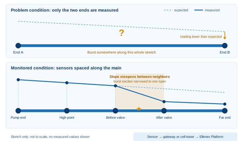
A burst appears as a break in slope. The span between two neighboring sensors that suddenly drops sharply is where crews should start, instead of walking the whole corridor.
Place sensors where the hydraulics change. Pump outlets, high and low points, either side of closed-in valves and branch offtakes tell you the most.
Let the transmitter filter. Sample often enough to catch surges, send only what matters, because the cell's rating counts readings and transmissions rather than years.
Match the network to the route. LoRaWAN with a private gateway suits clustered tapping points; NB-IoT/LTE-M suits points scattered along a corridor. Both land on the same platform.
How Far Can One Pressure Reading Speak for a Whole Main?
How far along a buried pipe can a single pressure reading be trusted to describe what the pipe is doing? On a short distribution loop the answer is usually far enough. On a transmission main that crosses farmland, passes under highways and follows long easements, the honest answer is only as far as the next change in ground height, valve position or demand. Closing that gap is the purpose of transmission main pressure monitoring: instead of one number at each end, you get a profile along the route.
Large-diameter mains carry treated water between sources, treatment plants, reservoirs and the start of distribution networks. There are far fewer of them than street-level pipes, yet each one carries so much water that a failure takes a large share of supply with it. Many are instrumented only at pump stations and reservoir inlets, so a burst in the middle is discovered through its consequences rather than its location.
Ellenex builds Underground Water Pipeline Pressure Monitoring around battery-powered pressure transmitters that attach to existing tapping points on buried mains and report over LoRaWAN or NB-IoT/LTE-M. This article stays at network scale: where sensors belong along a long main, how a hydraulic grade line turns their readings into evidence, and how that evidence narrows a burst to a single span. For the wider sector context, see Ellenex's overview of water infrastructure monitoring.
Chamber-level pressure control and radio behavior inside vaults are covered in the Ellenex post on pressure reducing valve chambers and pipeline monitoring, so this piece stays on the pipe itself.
Bursts on Long Mains: Costs That Accumulate Before Anyone Notices
Treated water lost along with its energy. Water escaping a main has already been pumped and treated, so every hour of an unnoticed leak wastes the electricity and chemicals behind it as well as the volume.
Supply lost to whole districts. A main that feeds several zones takes all of them down together, and a repair that begins late also ends late.
Damage that grows along the route. Escaping water undermines roadbeds, washes out pipe bedding and can reach neighboring utilities, so the bill rises with every hour of delay.
Small events that never trip a flow alarm. A weeping joint or a pinhole defect hides inside normal variation at the pump station until it becomes a burst.
Crews digging where water surfaces. Water often appears far from the actual defect, so excavation starts in the wrong place without a location estimate.
Obstacles That Come With Miles of Buried Pipe
Distance. Sites are far apart, so a manual check can cost a day's driving for a single reading.
Few places to sense pressure. Measurement is only possible where a tapping point, hydrant branch or valve fitting already exists; extra points cannot be added mid-route without excavation.
Natural pressure differences. Ground height alone makes readings differ from point to point, so a number from one site cannot be compared with another until the profile is understood.
Brief transient events. Pump starts and valve operations create short surges that infrequent sampling misses completely.
Uneven power and coverage. Main routes cross places with no mains electricity and variable cellular reception, which rules out wired telemetry at many sites.
Access and permits. Easements, traffic management and landowner notice make every site visit slow to arrange.
Transmission Main Pressure Monitoring Explained Through the Grade Line
The explanation below follows a reading from the water in the pipe to the screen of the person who acts on it. The hydraulics are general engineering practice; the hardware details come from Ellenex product documentation.
The Grade Line: A Pipe's Pressure Story Drawn Along Its Length
The hydraulic grade line is a simple idea. Plot the pressure energy of the water against distance along the pipe, adjusted for ground height, and you get a line that slopes gently downward in the direction of flow, because friction between water and pipe wall steadily uses up pressure. The slope steepens where more water is moving and flattens where less is. Every pressure sensor on the main supplies one point on that line.
When the pipe is healthy, the points sit on a line the operator already knows. When a burst opens somewhere along the route, extra flow rushes toward the break, and the line bends where the break is. That bend is the signal this whole approach is built to find.
A Sealed Gauge Element Reading the Water at the Tapping Point
The PTS3-L and PTS3-N transmitters use a sealed-gauge pressure element, so readings are taken relative to the atmosphere without a vent tube to keep clear. Wetted parts are stainless steel, and the process connection is chosen to match the fitting already on the main. Ranges are selectable, so the element can be matched to the pressures your main actually runs at.
Choosing Where Each Sensor Earns Its Place
Evenly spaced sensors are rarely the best layout. Sensors are most informative where the hydraulics change: at the pump outlet, at high points where pressure is lowest, at low points where it is highest, on either side of line valves and at major branch offtakes. Between those anchors, the grade line is predictable, so fewer sensors are needed. Where the route is long and straight, add intermediate points only as far apart as your repair crews can sensibly search.
Sampling Fast Enough for Surges Without Draining the Battery
Both transmitters sample periodically by default, with event-triggered sampling available as an option, and the interval can be changed over the air. Transmission can follow every sample or be conditional, so the unit can read frequently but only send when something noteworthy happens. That split between reading and sending is what lets a battery-powered device watch for surges across a long deployment.
Comparing Neighbors: How a Slope Break Points to a Span
The analysis is a comparison of neighbors. For each pair of adjacent sensors, the platform already knows the usual drop between them. A span whose drop suddenly becomes much sharper, with sensors beyond it reading lower overall, is the span that contains the break. The result is a narrowed search area rather than a surveyed point, and it should be cross-checked against pump and valve activity, since legitimate operations can bend the line too.
Two Routes From Tapping Point to Platform
On the LoRaWAN route, the transmitter sends compact radio packets to a nearby gateway, which passes them on via a network server to the Ellenex Platform. On the cellular route, the NB-IoT/LTE-M transmitter connects straight to the carrier's tower and needs no gateway. Payloads are encrypted on the LoRaWAN route. The knowledge centre explains the basics of LPWAN, LoRaWAN and NB-IoT/LTE-M if you want a primer.
What the Platform Does Once Readings Arrive
The Ellenex Platform at ellenex.net shows live values, historical trends and threshold alerts, with role-based, multi-tenant access so planners, operators and contractors can each see what they need. Readings can also flow out through an open API, webhooks or SCADA integration, and the Ellenex mobile app keeps the same view in a field engineer's pocket.
Running a Main That Reports Its Own Profile
Alarms arrive with a location. An alert names the span whose slope changed, not merely a pump station whose output fell.
First response starts closer to the break. Crews head to one span and bring the right valves and equipment with them.
Inspections follow evidence. Routine patrols concentrate on spans whose pressure behavior has drifted instead of covering the full route on a fixed calendar.
Surges become visible. Engineers can see how pump start-ups and valve closures actually behave on the line and adjust schedules accordingly.
One view for several teams. Operations, asset planning and contractors work from the same data under different permissions.
Shutdowns can be verified. Watching pressure fall and recover confirms that an isolation worked and that the repair held.
What Span-Level Visibility Is Worth Across a Main's Life
Fewer Drives Along Easements and Roadsides
Pressure arrives on a screen instead of requiring a visit, so trips happen when the data points to a span that needs attention.
Treated Water That Reaches Customers Instead of the Trench
A burst found sooner is a burst that loses less water, along with the energy and treatment already spent on it.
Pump Stations and Fittings Spared Repeated Shocks
Seeing surges lets operators soften start-up and closing routines, which reduces the hammering on joints, valves and pump equipment.
Crews Spared Blind Searches Near Traffic
A narrower search area means less time on exposed roadsides and fewer open excavations that turn out to be in the wrong place.
Shutdowns Scheduled Around the Break, Not the Whole Corridor
When the failed span is known, isolation can be limited to that section, which keeps more customers supplied during the repair.
Light Effort to Put in Place
Transmitters are shipped pre-configured and attach to existing tapping points, with no trenching for power or data cable. The financial case for IoT implementation walks through how such deployments are usually justified.
Hydraulic Data for Renewal Decisions
A long record of profiles shows which mains lose pressure faster than expected, which supports renewal priorities with measurement rather than age alone. It also feeds the broader water infrastructure monitoring view a utility builds across its assets.
Matching Ellenex Pressure Transmitters to Mains Problems
Surges and Slow Leaks From One Instrument
Configurable sampling means the same PTS3-L or PTS3-N can be set to watch for fast transients while still recording the slow drift that signals a developing leak. Event-triggered options keep the radio quiet until a threshold is crossed.
Housings for Buried Chambers and Valve Pits
Enclosure options include a compact housing with the sensor built in and versions where the electronics sit on a cable away from the sensing end, with or without an on-off switch. The sensing end is rated for immersion, which matters in pits that fill with water. The underground pipeline solution page lists the options in context.
Battery Capacity Counted in Readings and Transmissions
The replaceable lithium cell is rated by how many readings and how many transmissions it can support, not by a calendar span. A transmitter that reads often and reports only on events stretches that capacity much further than one that reports every sample, so the sampling plan matters as much as the cell itself.
Gateway Clusters or Cellular Along the Corridor
Where several tapping points sit close together, such as around a pump station or treatment works, a private gateway lets the LoRaWAN version share one backhaul and avoid per-device cellular fees. Where points are scattered along a corridor, the NB-IoT/LTE-M version connects each one straight to the carrier network, using a standard nano-SIM that works with any network provider.
Retuning Without Digging
Sampling and transmission settings can be changed remotely through downlink commands, so a sensor can move from a cautious routine to a rapid one when you are investigating a suspect span, then relax afterward.
Feeding SCADA and Hydraulic Models
Readings leave the platform through an open API, webhooks and SCADA integration, and the LoRaWAN version also works with third-party network servers. That keeps the data usable in the control room and in the hydraulic model your engineers already maintain.
Ellenex Underground Pipeline Solution: Mechanism and Outcome
Mechanism: a sealed-gauge pressure element at each tapping point senses line pressure and surges.
Mechanism: the transmitter decides what to send, then reports over LoRaWAN via a gateway or, on the cellular version, straight to the carrier tower.
Outcome: the platform assembles the readings into a pressure profile along the main and alerts on changes.
Outcome: operators gain a narrowed search area for bursts, visibility of surges and fewer routine site visits, as described on the solution page.
Specifying a Main-Line Sensor Without Reaching for Codes
Choosing a transmitter is a short list of decisions, and none of them needs an ordering code to discuss. This is general specification practice, applied to the Ellenex options.
Pressure range: pick a range that sits comfortably above the highest normal pressure plus an allowance for surges, and below the element's limit. Custom ranges can be requested.
Process connection: match the thread already on the tapping point so no adapters are needed.
Enclosure style: compact where the sensor sits in a dry spot, cable-separated where the sensing end must go deeper than the electronics.
Antenna: internal is the default on the cellular unit, with an external antenna available as a custom option; the LoRaWAN unit is offered with either.
Network: LoRaWAN where a gateway can serve a cluster, NB-IoT/LTE-M where each point needs its own link; the cellular version needs a carrier data subscription.
If you are unsure, the solution page is the best place to start, and the sales team can confirm available combinations for your pipeline.
Fitting a Sensor to a Live Main: General Field Practice
The points below reflect widely accepted industry practice for instrumenting pressurized mains. They are not Ellenex procedures, and your own utility standards come first.
Use an isolation valve at the tapping point so the sensor can be removed or replaced without taking the main out of service.
Bleed trapped air before connecting. Air pockets damp the signal and make early readings look noisy.
Mount so air cannot collect at the sensing face, which generally means avoiding fittings that sit at the top of the pipe or leave a pocket above the sensor.
Protect the cable from abrasion and sharp bends where it passes through chamber walls.
Record the elevation of each tapping point. Without it, readings from different sites cannot be placed on the same grade line.
Compare the first readings against a reference gauge and store photographs of the installation with the asset record.
A Corridor Where Trouble Has an Address
Once a transmission main reports its own pressure profile, the working day changes. Alerts name a span, crews arrive with the right isolation plan, and engineers review surge behavior on screen instead of guessing at it. Over time the stored profiles become a reference for the line's normal behavior, so a slow drift stands out long before it becomes a failure. The same mains that were once checked by driving their length are now understood by reading their slope.
Frequently Asked Questions
Why do two sensors on the same main read different pressures when nothing is wrong?
Ground height and friction both change pressure along a pipe. A sensor at a low point will read higher than one at a high point even in a perfectly healthy main, and a sensor further downstream will read lower than one near the pump.
That is why each tapping point's elevation should be recorded. Once heights are accounted for, the readings line up along the grade line and only genuine changes stand out.
Does a long main need a different pressure range than a distribution pipe?
It can. Transmission mains often run at higher pressures and see stronger surges than street-level pipes, so the range should cover the normal operating pressure plus a margin for transients.
Selectable and custom ranges are available on the Ellenex transmitters, so the choice can follow your line's actual behavior rather than a generic default.
What should I do about trapped air at a tapping point?
Bleed it before connecting the sensor and avoid mounting orientations that let a bubble collect on the sensing face. Air acts as a cushion and can hide short surges.
If readings look unusually smooth or noisy after installation, check for air first, because it is the most common cause of confusing early data.
Should sensors go at high points or low points along the main?
Both are useful for different reasons. High points show the lowest pressure on the route and warn first about loss of head, while low points show the highest pressure and take the greatest stress from surges.
Where tapping points are limited, prioritize the pump outlet, the highest point and either side of any line valve, then fill in between as access allows.
How quickly does a reading reach the dashboard?
In both cases the reporting interval you configure is the larger factor, so set the interval according to how fast an event on your main can unfold.
What do readings show while a main is drained for repair?
Pressure falls toward atmospheric as the main empties and rises again as it is refilled. The platform records the whole sequence, which makes it a useful check that isolation and recharge were done as planned.
Annotating the event in the platform keeps it from being mistaken for a fault in later analysis.
Can the readings feed a hydraulic model that we already maintain?
Yes. The platform exposes readings through an open API and webhooks and supports SCADA integration, so values can be pulled into a model or historian on your schedule.
Keeping the model calibrated against measured pressure at several points along the main is a common use of this kind of data.
Related Reading
LPWAN Solutions for Pressure Reducing Valve (PRV) Chambers and Pipeline Monitoring: how pressure control chambers are monitored and what changes underground.
Enhancing Water Infrastructure with Ellenex Industrial Pressure Sensors: the wider case for pressure sensing across water networks.
Most common technologies to monitor water pipeline leakage: an overview of leak detection methods and where pressure fits.
Advancements in Pipeline Pressure and Leakage Prevention: the energy angle on leakage in water utilities.
Useful Links
Talk to Ellenex
On the Ellenex sales inquiry page you can describe a transmission main in a few lines, including its route, the tapping points already in place and who needs to hear first when it misbehaves, and the team will reply with a suggested sensor layout and connectivity plan. Where your pipeline also supports wider infrastructure monitoring, mention that too.


