

Retire the Filter Calendar With HVAC Filter Differential Pressure Monitoring


Key Takeaways
Measure resistance, not time: HVAC filter differential pressure monitoring tracks how hard air must push through each filter bank, so changes follow the media's condition, not a date.
Know the two reference points: record a clean-filter baseline at installation and set the change alert near the final resistance the filter maker recommends, then let the trend show the gap closing.
Treat a sudden fall as an alarm: pressure that drops when it should be climbing usually points to torn media, a missing filter or air sneaking around the frame.
Read pressure alongside fan duty: on variable-speed systems, compare readings taken at similar fan speeds before deciding a filter is loaded.
Choose the network by layout: a private LoRaWAN gateway suits air handlers on one campus; NB-IoT/LTE-M suits units spread across many buildings.
Clean Filters Are Built to Get Dirty, and That Is the Point
Every air filter in a building is designed to clog. It exists to hold back dust, pollen and fine particles, and each particle it keeps adds a little resistance to the air passing through. HVAC filter differential pressure monitoring turns that slow, invisible process into a number the maintenance team can watch: the pressure on the dirty side of the filter compared with the pressure on the clean side.
That comparison answers the question every facilities team argues about, which is when a filter has actually finished its working life. Change it too soon and good media goes into the dumpster. Change it too late and the fan spends months shoving air through a blanket, while unfiltered air may start finding its way around the frame.
Ellenex addresses this with its air filter performance monitoring solution for industrial HVAC, built on battery-powered differential pressure transmitters that report each filter bank to the Ellenex Platform.
This article stays with the filter itself: when to change it and how to keep its reading honest. Duct-by-duct air delivery is covered in the article on HVAC airflow monitoring, and sensor-level detail lives in the earlier post on wireless differential pressure sensors for AHU filter performance monitoring.
Changed Too Early, Changed Too Late: The Price of Guessing
Media thrown away half used: calendar-based programs replace every filter on the same day, whether it sat in a lightly used wing or beside a loading dock.
Fans fighting a loaded bank: once a filter passes its useful life, the fan works harder to move the same air, or the system quietly delivers less of it. Either way, energy or comfort is lost, and nobody sees which.
Bypass that looks like a clean filter: a filter that tears, collapses or slips in its frame lets air take the easy path. The local gauge may even look better than before, so the fault can sit unnoticed until coils foul or occupants complain.
Coils collecting the dust instead: particles that pass a failed stage settle on cooling coils, fan blades and duct walls, where cleaning costs far more than a filter.
Air quality promises without evidence: hospitals, laboratories, data halls and food plants often need to show that filtration was maintained. A clipboard entry saying a filter was changed proves little about the months between visits.
Filter Banks Sit Where Nobody Looks
Hidden inside casings and on rooftops: filters live behind access panels, inside rooftop units and in plant rooms that technicians visit only when something breaks.
Small pressures that move slowly: filter resistance builds gradually and is small in absolute terms, so a coarse instrument or a drifting zero can bury the trend.
Airflow that changes all day: variable-speed fans raise and lower the pressure across a filter as demand shifts, which can look like loading or cleaning when the filter has not changed at all.
Several stages loading at different rates: a pre-filter, a secondary filter and a high-efficiency final stage each fill at their own pace, so one reading cannot speak for the whole bank.
Gauges that only report to passers-by: a dial gauge on the casing shows the current value to whoever happens to stand in front of it, and keeps no history at all.
Estates spread across many buildings: a portfolio with dozens of air handlers turns every manual check into a drive, a ladder and a panel to unscrew.
Reading a Filter Bank Through HVAC Filter Differential Pressure Monitoring
Any differential pressure measurement compares two pressures and reports the gap; the earlier explainer on how differential pressure sensors work covers the physics. Here is how that applies to a filter bank.
Upstream and Downstream: Two Tubes Across the Media
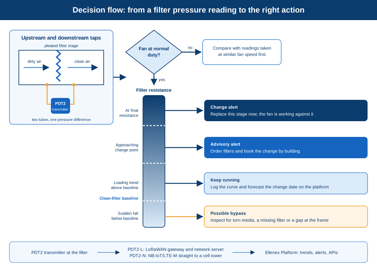
A filter transmitter has two process ports. Flexible tubing runs from one port to a tapping point on the dirty-air side of the filter and from the other port to a tapping point on the clean-air side. The transmitter reports the difference between them, which is the resistance the filter adds to the airstream. As a widely followed practice, the taps sit close to the filter face but away from bends, dampers and fan inlets, so turbulence does not distort the reading.
A Thermal Micro-Flow Element Feels the Difference
According to the solution datasheet, the sensing element is a micro-thermal differential pressure sensor with an internal micro-flow channel. A tiny amount of air moves through that channel in response to the pressure difference, and the element senses it thermally rather than by flexing a large diaphragm. The datasheet credits this measurement principle with zero-point drift stability, which matters for a reading that changes gradually over many months. Both the PDT2-L and PDT2-N transmitters also include a built-in temperature sensor.
Bi-Directional Sensing for Positive and Negative Plenums
A filter bank before the supply fan sits below atmospheric pressure; one after the fan sits above it. Both PDT2 variants measure bi-directional differential pressure, so the same transmitter works on the suction or discharge side and still reports the gap across the media.
The Clean-Filter Baseline and the Final Resistance Point
Every filter has two reference points that turn raw readings into decisions. The first is the clean-filter baseline, recorded on the platform when fresh media goes in at normal fan duty. The second is the final resistance the filter manufacturer recommends as the point to replace it, which is printed on most filter documentation. Widely accepted maintenance practice is to set the change alert at or slightly below that final value and to plan the order as the trend approaches it.
Telling Filter Loading From Fan Speed Changes
On a constant-volume system, rising resistance means loading. On a variable-speed system, resistance also rises and falls with fan speed. Common practice is to compare readings taken at similar fan duty, such as the same occupied period each day, or to bring the fan speed signal from the building management system onto the platform beside the filter trend.
Pre-Filter, Secondary and High-Efficiency Stages
The solution datasheet describes monitoring across primary, secondary and HEPA filters. Each stage gets its own transmitter, because a cheap pre-filter often loads quickly while protecting a costly final stage that loads slowly; separate trends stop the long-lived filter being swapped out with the short-lived one.
Off the Plant Room Floor: Gateway or Tower
The transmitter takes readings on a configurable schedule and can send each reading, only readings that cross a condition, or both. PDT2-L sends over LoRaWAN to a private gateway, which passes data through the network server to the platform. PDT2-N uses NB-IoT/LTE-M to reach a cellular tower directly, with no gateway on site. The trade-offs between the two are set out in the earlier comparison of LoRaWAN and NB-IoT for industrial monitoring.
Platform Work: Loading Trends and Change Forecasts
On the Ellenex Software Platform, each filter's readings become a loading curve. The solution datasheet describes reporting filter loading status, estimating filter efficiency, predicting particulate buildup and flagging clogging trends, alongside threshold alerts and historical logs. In daily use, that means a list of air handlers ranked by how close each bank is to its change point, rather than a calendar that treats them all the same.
Maintenance Rounds Built Around Filter Condition
Work orders raised by the filter: a change request is triggered when a bank approaches its final resistance, not when a date arrives.
Failures spotted the day they happen: a torn or displaced filter shows up as a sudden fall in pressure, so bypass is investigated before dust reaches the coil.
One screen for a whole estate: every air handler across campuses or buildings reports to the same dashboard, with history kept for each stage.
Filter orders matched to real use: procurement sees which units load fastest and stocks the right sizes ahead of need.
Evidence ready for audits: a continuous pressure record shows that filtration stayed within its limits between visits, which a sign-off sheet cannot.
Filter Spend, Fan Power and Air Quality on One Ledger
Filter monitoring pays back across several separate budgets. For the wider economics, see Ellenex's IoT cost-benefit guide; the points below are specific to filter banks.
Ladder Climbs and Panel Removals Cut Back
Checking a filter by hand means a ladder, a roof hatch or a screwed access panel. Remote readings leave only the visits where something needs doing.
Filter Media Used to the End of Its Useful Life
Replacing filters on condition lets lightly loaded banks stay in service until they have used their holding capacity. Fewer filters bought means less spent on media, less handling and less waste sent to landfill.
Fans and Coils Spared From Avoidable Strain
A heavily loaded filter forces the fan to work harder, and a failed filter lets dust settle on coils and fan blades. Changing at the right time protects the equipment that is far more expensive to clean or replace than the filter.
Healthier Air for the People Inside
Filters that are neither overloaded nor bypassed keep particulate out of occupied spaces. In clinics, laboratories and production areas, that also protects processes and people who depend on clean supply air.
Filter Orders and Labor Booked in Advance
Loading curves show which units will need attention in the coming weeks. Purchasing and maintenance can batch changes by building and avoid emergency call-outs.
A Small Install on a Running Air Handler
Battery power and wireless reporting mean no cable runs back to a controller. The transmitter mounts beside the casing, two tubes reach the tapping points, and readings start arriving once the device checks in.
Evidence for Filter Grade and Supplier Choices
Loading histories by unit and filter type give real data for comparing grades or suppliers.
Where PDT2-L and PDT2-N Fit Each Filter Bank Problem
Sealed Housings for Rooftops and Plant Rooms
Rooftops and damp plant rooms are hard on electronics. Both PDT2-L and PDT2-N are designed for outdoor use, with a weather-sealed, UV-protected enclosure, so the transmitter can sit next to the unit it watches.
Sensitivity Suited to Small Filter Pressures
Filter resistance is a low-pressure measurement. Both variants offer a standard low range and an even lower optional range for fine differential pressures, and suit air, inert gases and other media that neither conduct electricity nor corrode. The solution datasheet highlights zero-point stability, which keeps a slow loading trend from being masked by sensor drift.
Fan-Speed Swings Handled by Configurable Sampling
Reading intervals and transmission conditions are adjustable remotely on both variants, so a unit with large daily fan swings can report more often than a steady constant-volume one. High and low alarm thresholds are adjustable remotely on the platform, with no trip to site.
One Transmitter per Stage
Each transmitter measures one pressure difference, so a multi-stage bank gets one device per stage, each with its own trend and alerts.
Battery Planning Counted in Readings and Transmissions
Both variants run on a replaceable internal lithium battery, with an optional external supply. Ellenex rates battery capacity by the number of readings taken and messages sent rather than by calendar time, so the real service life of each transmitter depends on the sampling interval and sending rules chosen for that filter bank. A transmitter that reports a slowly loading filter only occasionally will run much longer than one sending constant updates.
Private Gateway on a Campus, Cellular Across a Portfolio
Where many air handlers share one site, such as a hospital campus or a factory, one private LoRaWAN gateway serves all the PDT2-L transmitters without per-device data plans. Where units are scattered across stores, schools or regional offices, PDT2-N connects each one through NB-IoT/LTE-M to the nearest cellular tower, with nothing extra to install on site.
Alerts and Records That Replace the Walk-Past Glance
The platform sends multi-channel alerts, keeps every reading and offers open APIs and webhooks for a building management system, SCADA or maintenance software. The Ellenex mobile app and the web platform at ellenex.net give technicians the same view in the field and at the desk.
Ellenex Filter Monitoring, Part by Part: Mechanism and Outcome
A dual-port differential pressure transmitter measures the gap across each filter stage.
Outcome: filter condition becomes a continuous, comparable number for every bank.
A stable thermal micro-flow sensing element and a weather-sealed enclosure. Outcome: slow loading trends stay readable over long service periods, indoors or on the roof.
Configurable sampling, transmission conditions and alarm thresholds. Outcome: alerts arrive as a bank nears its change point, and sudden falls are flagged as possible bypass.
LoRaWAN through a site gateway, or cellular NB-IoT/LTE-M straight to a tower. Outcome: one campus or a nationwide portfolio reports to the same platform.
The Ellenex Platform with trends, forecasts, alerts and APIs.
Outcome: filter changes, orders and audits are planned from data, as part of wider infrastructure monitoring.
Picking Range, Antenna and Power for a Filter Transmitter
A few choices made before ordering decide how well a filter transmitter fits its location.
Pressure range: the standard range suits most supply and return filter banks. The lower optional range suits fine pressure work, such as a single lightly loaded stage or a room-pressure application, and other ranges are available on request.
Network variant: choose the LoRaWAN variant where a gateway can cover many units on one site, and the NB-IoT/LTE-M variant where units are isolated or a gateway is impractical.
Antenna: an internal antenna keeps the unit compact in open plant areas, while an external antenna helps when the transmitter sits inside a metal-clad plant room or a deep rooftop enclosure.
Power: the internal battery suits most filter banks. An external supply with battery backup is an option where mains power is already close to the air handler and frequent reporting is wanted.
Installation kit: an optional differential pressure kit supplies a static pressure tip, connector and valve for the tapping points.
Tubing Errors and Other Reasons a Filter Reading Misleads
Most odd filter readings come from the installation rather than the transmitter. These checks follow general industry practice.
Tubes swapped between ports: if the dirty-side tube goes to the wrong port, the sign of the reading flips. The bi-directional measurement still works, but alerts set for a rising value will never fire.
Kinked, cracked or loose tubing: a pinched tube damps the reading, and a leaking connection pulls it toward room pressure. Run tubing with gentle bends and check fittings at every filter change.
Taps in turbulent air: a tapping point just after a fan inlet, damper or sharp bend picks up swirl rather than steady pressure. Moving the tap to a calmer section usually settles a noisy trend.
No new baseline after a change: if the clean-filter baseline is not refreshed when new media goes in, the platform keeps comparing against the old filter. Record it at normal fan duty soon after each change.
Ignoring a falling trend: a reading that drops while the filter is meant to be loading is a warning, not good news. Check for torn media, a missing filter or a gap around the frame.
An Estate Where Filters Ask to Be Changed
With HVAC filter differential pressure monitoring in place, the calendar stops deciding when filters come out. Each bank reports its own resistance, units are ranked by how close they are to their change point, and technicians arrive with the right filters. Bypass shows up as a clear anomaly, fans stop pushing against overloaded banks, and every change is on record for audits. The same transmitters and platform also extend to duct airflow measurement, critical room pressure control and dust collector monitoring, so filter data becomes one part of a broader view of the building.
Frequently Asked Questions
Why does the pressure across a filter rise as it loads?
As particles collect in the media, the open paths for air become narrower and fewer. The fan has to create a larger pressure difference to push the same amount of air through, and that larger difference is exactly what the transmitter measures.
The rise is usually slow at first and quickens as the media fills, which is why a trend says more than a spot reading.
What does a sudden fall in filter pressure usually mean?
A filter that is loading should show a steady or rising trend. A sharp fall usually means air has found an easier route, through torn media, a collapsed pleat, a filter that has slipped out of its track or a door left open on the casing.
Check the fan duty at the same moment. If the fan has not slowed, treat the drop as possible bypass and inspect the bank.
How do I set a change alert from the filter maker's recommended final resistance?
Start with the final resistance printed on the filter documentation and set the change alert at or slightly below it, so there is time to order and schedule the work. Many teams add an earlier advisory alert as the trend approaches that value.
After the first full filter life, compare where the alerts fired with how the filters looked when removed, and adjust thresholds remotely from that evidence.
Does each filter stage in an air handler need its own transmitter?
Yes, if you want to know which stage needs changing. Each transmitter measures the difference between two points, so one device per stage keeps the pre-filter, secondary and final filters on separate trends.
One transmitter across the whole bank can warn that total resistance is high, but not whether the cheap pre-filter or the costly final filter is responsible.
Will readings change when a variable-speed fan slows down at night?
Yes. The pressure across a filter depends on how much air passes through it, so a slower fan produces a lower reading even though the filter itself has not changed.
To judge loading, compare values taken at similar fan duty and set alert thresholds for the normal operating condition.
Can the transmitter sit outdoors next to a rooftop unit?
Both PDT2 variants are designed for outdoor installation, with a weather-sealed, UV-protected enclosure. The transmitter can be mounted beside the rooftop unit, with tubing run through the casing to the tapping points.
As general practice, route tubing so rainwater cannot run along it into the ports, keep it clear of hot exhaust surfaces and secure it against wind.
How soon after a filter change can the baseline be trusted?
Record the baseline once the new filter is seated, the access panels are closed and the fan has returned to its normal duty. Readings taken with a door open or the fan ramping up will not represent the filter.
A typical value from the first day of readings is more reliable than the very first one, and on variable-speed systems it should come from the same operating period as the change alert.
Related Reading
Wireless Differential Pressure Sensors for AHU Filter Performance Monitoring: wireless sensors on air handling unit filters.
Optimizing Air Filter Performance in HVAC Systems with Ellenex's NB-IoT Technology: the cellular route for distributed buildings.
How to Find the Optimal Time to Replace Your Air Filter: the energy and cost side of replacement timing.
Duct by Duct: How HVAC Airflow Monitoring Replaces Guesswork: air delivery measured duct by duct.
Useful Links
Talk to Ellenex
Your filter invoices already hint at which air handlers are changed too often and which are left too long. A short pilot on a handful of those units is the quickest way to swap that hint for a measured loading curve, and the Ellenex team can help scope it, from transmitter choice to first alert levels, through the sales inquiry page. The full component list is on the Ellenex air filter performance monitoring solution page.


